
RGB LIGHT


Project-01 [Display red,green,and blue color using RGB and Sajilobot]
Introduction:
An RGB led is a type of led consisting of three primary color led in one unit Which can display any possible color by combining hex values of color.the objective of this experiment is used to display Red green and Blue colors
Materials Required:
Sajilobot
Jumper wires
Data transmission cable
RGB sensor
Jumper wires
100 ohm resistor
Circuit diagram:
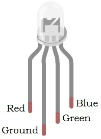
There are 4 pins on the RGB with a longer ground pin separating red and green channel, the remaining channel is for Blue.

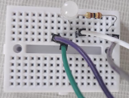
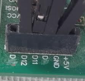
Connect The pins as shown in the fig above and remember the Digital pins for each color.We will use that later in code to send color values.
RGB values:
The RGB values stand for Red, Green, Blue color values. It ranges from (0 to 255)
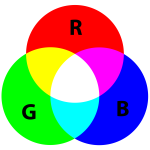
To display red color we can take red value as (255) and both green/blue value as (0)
To display green color we can take green value as (255) and both red/blue value as (0)
To display blue color we can take red value as (255) and both red/green value as (0)
mBlock color picker:
Let's create a color picker in Mblock to mix and Match RGB colors
Step-1:- open mBlock, Delete unnecessary Sprites, and devices
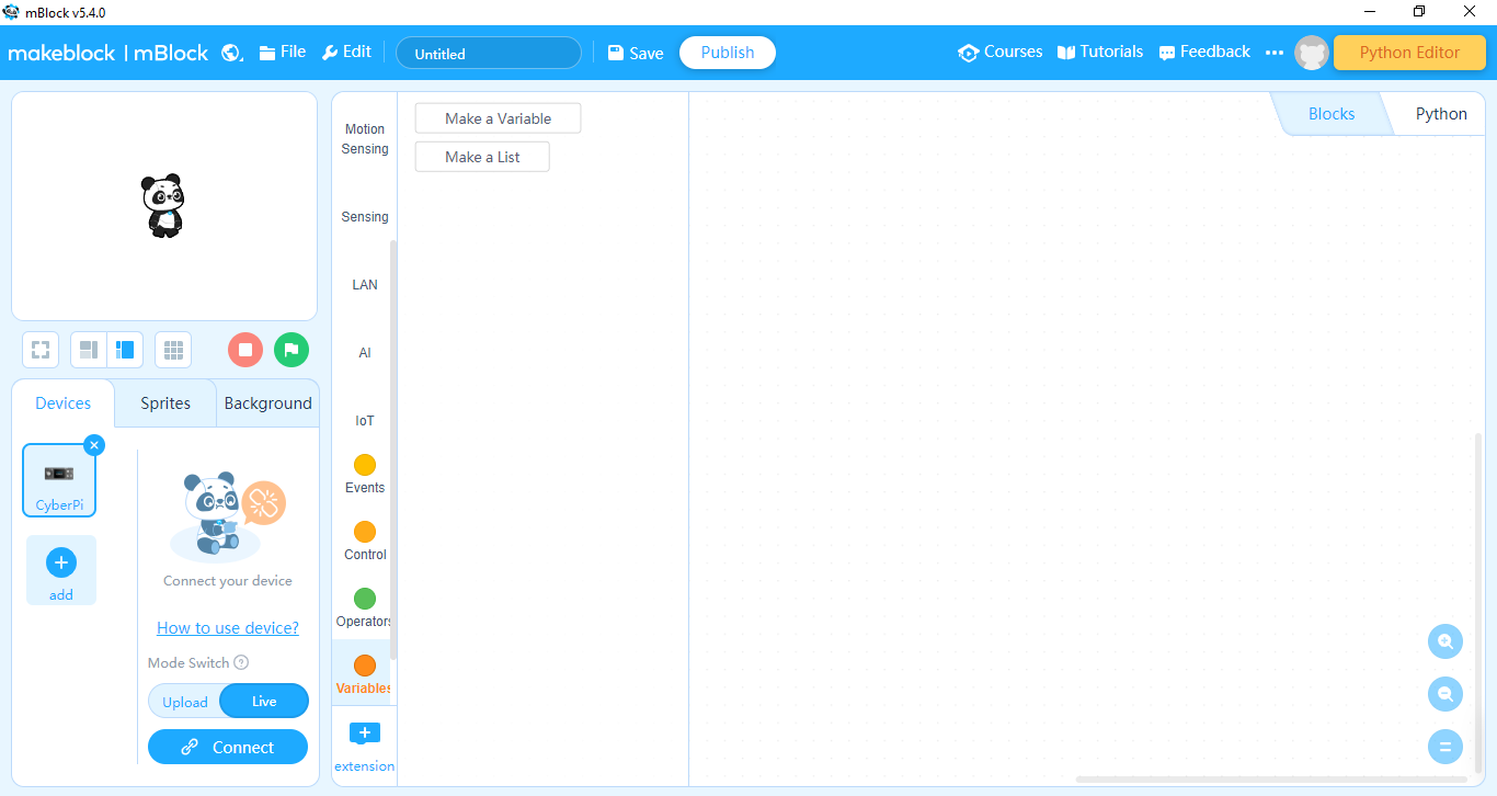
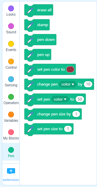
Step- 2- Create a blank sprite called Screen, add pen extension
Step-3;- Create & variables for Red, Green 4 Blue Respectively, convert the variable display to slider.
Step-4 :- Add the following code:-.

Task:Mix colors to display using RGB light
Code:
The code for the project is given below:
// Define pins for each color,as connected in above circuit
const int red_pin=13;
const int green_pin=12;
const int blue_pin=11;
void setup() {
// Declare pinmode to set pins as output for receiving our signal
pinMode(red_pin, OUTPUT);
pinMode(green_pin, OUTPUT);
pinMode(blue_pin, OUTPUT);
}
void loop() {
setcolor(255,0,0); // sets color to red
delay(1000); // displays red color for 1 second
setcolor(0,255,0); // sets color to green
delay(1000); // displays green color for 1 second
setcolor(0,0,255); // sets color to blue
delay(1000); // displays blue color for 1 second
}
void setcolor(int R,int G,int B) // we are creating a function called setcolor which selects the RGB values and sends signals accordingly
{
analogWrite(red_pin,R); // Writing values to red color pin
analogWrite(green_pin,G); // Writing values to red color pin
analogWrite(blue_pin,B); // Writing values to red color pin
}
UPLOAD
Select Arduino uno as board and set the port as connected to your computer.
Result
We were able to display red, green and blue colors for 1 second each.

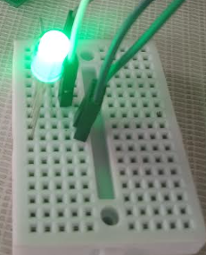

Fig: outputs
Project-02 [Display various colors using RGB sensor and Sajilobot]
Introduction:
An RGB led is a type of led consisting of three primary color led in one unit Which can display any possible color by combining hex values of color.the objective of this experiment is used to display Red green and Blue colors
Materials Required:
Sajilobot
Jumper wires
Data transmission cable
RGB sensor
Jumper wires
100 ohm resistor
Circuit diagram:
There are 4 pins on the RGB with a longer ground pin separating red and green channel, the remaining channel is for Blue.
Connect The pins as shown in the fig above and remember the Digital pins for each color.We will use that later in code to send color values.
Color codes:
Using mBlock mix RGB to produce various colors and modify the code to display these colors
Examples colors:
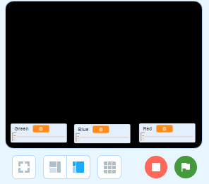
lets find these colors using our color picker

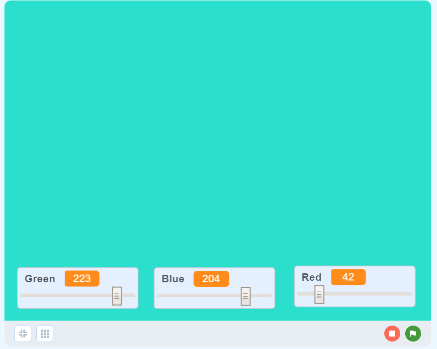


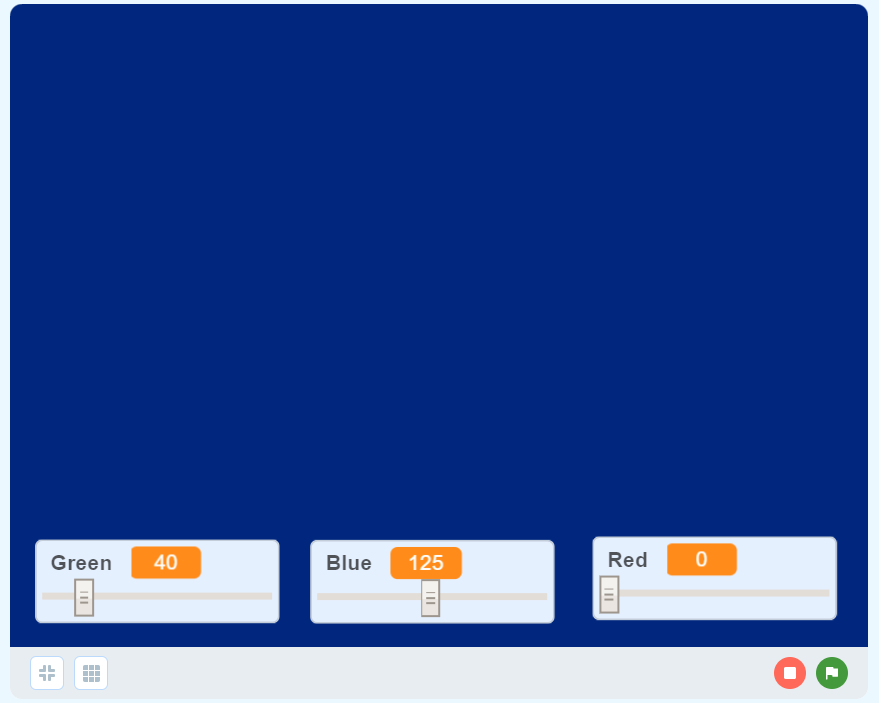
We found the colors from above image by using the sliders,let's write RGB values for each color
Color 1 = R(42)G(223)B(204)
Color 1 = R(111)G(217)B(255)
Color 1 = R(219)G(19)B(58)
Color 1 = R(254)G(70)B(10)
Color 1 = R(0)G(40)B(125)
Code:
The code for the project is given below:
// Define pins for each color,as connected in above circuit
const int red_pin=13;
const int green_pin=12;
const int blue_pin=11;
void setup() {
// Declare pinmode to set pins as output for receiving our signal
pinMode(red_pin, OUTPUT);
pinMode(green_pin, OUTPUT);
pinMode(blue_pin, OUTPUT);
}
void loop() {
setcolor(42,223,204); // sets color to color 1
delay(1000); // displays red color for 1 second
setcolor(117,217,255); // sets color to color 2
delay(1000); // displays green color for 1 second
setcolor(219,19,58); // sets color to color 3
delay(1000); // displays blue color for 1 second
setcolor(254,70,10); // sets color to color 4
delay(1000); // displays blue color for 1 second
setcolor(0,40,125); // sets color to color 5
delay(1000); // displays blue color for 1 second
}
void setcolor(int R,int G,int B) // we are creating a function called setcolor which selects the RGB values and sends signals accordingly
{
analogWrite(red_pin,R); // Writing values to red color pin
analogWrite(green_pin,G); // Writing values to red color pin
analogWrite(blue_pin,B); // Writing values to red color pin
}
UPLOAD
Select Arduino uno as board and set the port as connected to your computer.
Result
We were able to display 5 colors for 1 second each [Try yourselves for the effect]


![Game Codes [Notes]](https://lh4.googleusercontent.com/CafB8mQNrZkSEI4TNGcfGmqTU0anmyTXrrYgWnukMWIpTMch_SJa5Y_g3bBjpIFcuwin5zU7fvMPI9vWsER1ztDL16nV2MqkfuMRg_Mm1lPVax-UnSe2WwjoMT32ICjprrgIRH7cJV74Y7ykQVJky3S6sJf-CWEG=w72-h72-p-k-no-nu)


0 Comments